Objective 1 –Define the terms: ionic bonding, covalent bonding, bond length, dipole moment*, and lattice energy.
* Dipole Moment will be discussed with objectives 3 and 4
Chemical Bonding
Chemical bonds are the forces that hold atoms together. Bonding occurs because the system can achieve the lowest possible overall potential energy condition by forming the bonds. Let’s consider the simplest bonding situation possible: two hydrogen atoms bonding together to form an H2 molecule.
Each hydrogen has a nucleus with a +1 charge and an electron with a -1 charge. The nuclei and electrons are the same, so the electrons will be attracted to both nuclei equally. The two positives will repel each other, and the two electrons will repel each other.
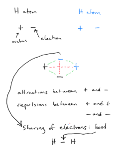
The lowest overall potential energy condition results when the nuclei and electrons are positioned in such a way to maximize the benefit of the nuclear/electron attractions and minimize the effect of the electron-electron and nucleus-nucleus repulsions. In the H2 molecule (or any molecule), the atoms will position themselves such that the positively charged nuclei and negatively charged electrons interact for the lowest possible energy. The resulting distance between the nuclei is the bond length.
The electrons are essentially shared between the nuclei. This sharing of the two electrons is a chemical bond. It is represented by a single line between the H’s (chemical symbol for hydrogen) to represent the bond between the atoms in the structural formula.
The energy required to pull the atoms out of the bonding situation, isolating them as separate atoms, is the bond energy. We can think of the bond energy as the energy required to break the bond.
Types of Chemical Bonds
In the first unit, we looked at two general types of bonding: ionic bonding and covalent bonding. These were covered in the Bruce’s Notes for Atoms, molecules, and ions. The information from the Bruce’s Notes will be reviewed briefly as it is expanded on in the new material below.
Ionic Bonding
Ionic compounds are made up of positive cations and negative anions existing in the necessary ratio to balance the charge. The simplest ionic compounds are made up of a metal cation and a nonmetal anion. We can think of an ionic bond as the electrostatic attraction between a positive cation and a negative anion.
An example of an ionic compound is NaCl (sodium chloride). NaCl does not consist of individual molecules made up of one Na atom and one Cl atom. In NaCl, the sodium is Na+ ions and the chlorine is Cl– (chloride) ions. Rather than existing as molecules, they exist in a repeating structure called a crystal lattice. This lattice has a 1:1 ratio of sodium ions to chloride ions. Now we can look at it in terms of electron configuration.
Na has an electron configuration of [Ne]3s1. Losing one electron to form the Na+ ion will take it to the noble gas configuration. Cl has an electron configuration of [Ne]3s23p5. Gaining one electron to form the Cl– ion will take it to the noble gas configuration. We can think of the Na atom as losing one electron to the Cl atom. In ionic bonding, valence electrons from a metal atom are transferred to a nonmetal atom, so that both ions have a noble gas configuration. The resulting ions are attracted to each other, forming the ionic bond.
CaCl2 has a ratio of one Ca2+ ions to two Cl– ions. The 1:2 ratio is needed to balance the charges for a neutral compound. Let’s look at in in terms of electron configuration.
Ca has an electron configuration of [Ar]4s2. Losing two electrons to form the Ca2+ ion will take it to the noble gas configuration. Cl has an electron configuration of [Ne]3s23p5. Gaining one electron to form the Cl– ion will take it to the noble gas configuration. We can think of the Ca atom as losing one electron to one Cl atom and another electron to another Cl atom (resulting in the 1:2 ratio of Ca to Cl)
Lattice Energy
Remember, though, that ionic compounds to not exist as molecules, they exist in a repeating structure called a crystal lattice. The cations are surrounded by anions and vice-versa, making these compounds very stable. Lattice energy is the energy required to completely separate a mole of solid ionic compound into its gaseous ions
NaCl(s) → Na+(g) + Cl-(g) ΔH = +788 kJ/mol
The magnitude of the lattice energy depends upon the charges of the ions, their size and the particular lattice arrangement. You are not responsible for doing numerical lattice energy calculations, but you should understand the concept and definition of lattice energy.
Covalent Bonding
Covalent bonding generally takes place between two nonmetal atoms. In covalent bonding, the molecules share electrons. This contrasts with ionic, in which one atom loses the electron(s) to another.
In pure covalent bonding, the bonding electrons shared equally. H2 (which we looked at previously) is an example.
In polar bonding or polar covalent bonding, the bonding electrons are shared unequally. The bonds between hydrogen atoms and oxygen atoms in water is an example. In the O-H bond, even though O and H share electrons, O gets the shared electrons more than H.
We will spend most of this topic with a detailed look at covalent bonding beginning with Objective 6.
Objective 2: Write the electron configuration of ions of the s- and p-block elements.
This objective was covered in our previous topic of Electronic Structure of Atoms
Objective 3: Define electronegativity and relate the electronegativity of an atom to its position in the periodic table.
Electronegativity
Ionic, covalent, and polar bonds all involve sharing of electrons between the bonding atoms, but they differ by degree of sharing. Earlier, we saw that in a Na-Cl bond, electrons were not shared (they were transferred from Na to Cl). The electrons in an H-H bond were shared equally, and in an O-H bond they were shared unequally.
We can tell how much (or little) sharing of electrons will occur between bonding atoms using electronegativity. Electronegativity is the ability of an atom to attract shared electrons to itself. Each element (with the exception of the noble gases) has a calculated electronegativity value ranging from 0.7 to 4.0. There values are shown in OpenStax Figure 7.6 and in many other interactive periodic tables you might find online. The atom with the higher electronegativity wants the shared electrons more.
Looking at Figure 7.6 , you can see the periodic trends in electronegativity – it increases from left to right along a period (on a row). Also, the representative elements, the electronegativity decreases as you go down a group (column). Therefore, electronegativity increases as you go up and right on the table (toward fluorine). As we will see later, knowing these trends can quickly give us information without having to look up the values.
Objective 4: Predict relative bond polarities
Objective 5: Classify a bond as nonpolar covalent, polar covalent, or ionic based on the differences in electronegativity
The difference in electronegativity values of the two bonding atoms (also called electronegativity difference or simply Δ) tells us how ionic or covalent the bond is. The lower the difference, the more covalent the bond. The larger Δ is, the more ionic character the bond has. We also say that the higher Δ is, the higher polarity the bond has.
Let’s look at the bonds we considered in the previous objective, using the values in Figure 7.6:
Na-Cl: Δ=3.0-0.9=2.1
O-H: Δ=3.5-2.1=1.4
H-H: Δ=0 (it will always be 0 if the atoms are the same)
Of these three, the polarity increases as we go from H-H to O-H to Na-Cl.
A general guideline for categorizing bonds as ionic, polar covalent, or covalent is in Figure 7.8 in OpenStax.
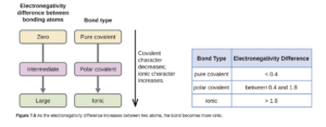
Using that, we would categorize H-H as pure covalent, O-H as polar covalent, and Na-Cl as ionic. While it is tempting to rely strictly on this chart, it is just a general guide and can be misleading – read the sentences directly below Figure 7.8 for guidance. Generally, it is best to think of bonding as a continuum, with all bonds having some ionic and some covalent character.
Example 7.3 in OpenStax shows a good example of the application of electronegativity difference.
Dipole moments
The quantitative measure of the magnitude of polarity of a bond is called its dipole moment. It is larger for larger Δ.
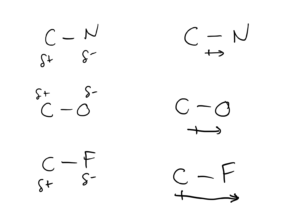
Dipole moments are commonly represented in two ways:
- δ+ and δ- indicates partial positive and negative charges. If this is used, the more electronegative atom is the negative end of the dipole.
- An arrow with a “plus sign”. The plus sign designates the positive end of the dipole (the less electronegative atom). A longer arrow indicates higher polarity.
The diagram below shows these methods for C-N, C-O, and C-F bonds.
Objective 3-5 practice
Objective 6: Write the Lewis Dot Structures of covalent compounds and polyatomic ions.
Lewis Dot Structures show arrangement of atoms and valence electrons in molecules. For example, a Lewis Dot Structure of the H2 molecule is:
H-H
As was discussed in the earlier objectives, the line between the two hydrogen atoms symbolizes a two electrons being shared between the hydrogen atoms. A hydrogen atom has one valence electron or an electron configuration of 1s1. But if the hydrogen atoms share their electrons, each hydrogen can have 2 electrons next to it – like a helium atom, which has noble gas configuration of 1s2.
This is the underlying principle behind Lewis Dot structures – atoms will arrange themselves in molecules and bond by sharing electrons to try to attain a noble gas configuration of valence electrons around them. For hydrogen that means 2 valence electrons (1s2, like He).
Most elements, like C→F and below want 8 valence electrons (ns22p6, like Ne, Ar, Kr, etc) and will arrange themselves on dot structures to do that. This is known as the octet rule.
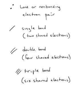
Bonding and Lone Pair Electrons
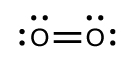
Here is an example of a Lewis dot structure of carbon dioxide:
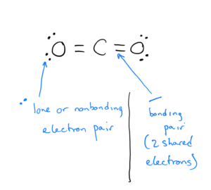
- Electrons that are shared by atoms are called bonding pairs. Each line signifies two shared electrons.
- Electrons that are not shared by atoms but belong to a particular atom are called lone pairs or nonbonding pairs and are signified by two dots (each dot is one electron).
In carbon dioxide, the C to O bonds are shown as double lines – these are double bonds, which are for shared electrons.
In CO2, the carbon atom and each of the oxygen atoms are surrounded by 8 valence electrons, satisfying the octet rule.
Symbols in Lewis dot structures
How to write Lewis dot structures
There are many approaches, procedures, and resources available to help you learn to write Lewis dot structures. They may differ slightly, but they are all designed to get to the goal of a correct structure for the compound or molecule of interest. I don’t care which you use as long as you understand how to write them. Resources include:
- Section 7.3 in OpenStax has a detailed step-by-step procedure along with many step-by-step worked out examples
- Googling “Lewis dot structure of (compound formula)” will lead you to numerous videos showing you how it is done (be careful to use those from a reputable source)
- Here is a link to a procedure for writing Lewis Dot structures. This procedure is also shown directly below, so you have the option of reading it here or opening it in a different browser tab to refer to.
Procedure for writing Lewis dot structures
First, predict the arrangement of the atoms:
- The first atom in the formula will usually be the central atom, unless the first atom is hydrogen. Hydrogen always goes on the end. If the first atom in the formula is hydrogen, then the least electronegative atom will usually be the central atom.
- Usually, molecules with symmetrical formulas will have symmetrical atomic arrangements. For example, S2Br2 has the following arrangement: Br – S – S – Br
- For acids containing oxygen, the oxygens are bonded to the central atom and the hydrogens are bonded to the oxygens.
Then, complete the Lewis dot structure by adding bonds and lone pair electrons.
- Determine the total number of valence electrons available in the molecule. To do this: first add together the valence electrons for each atom, then add or subtract electrons (if necessary) to account for a charge on the molecule
- Place single bonds between each atom. Remember, each single bond counts as two valence electrons
- Place the remaining valence electrons from part a. around the atoms surrounding the central atom, to form octets.
- Place any remaining electrons on the central atom as lone pairs.
- Count the electrons on the central atom. If the central atom does not have an octet, you may need to try a multiple order (double or triple) bond or bonds. C,N,O,and S often form multiple order bonds.
- When you are finished with the structure, check to make sure the number of electrons in your Lewis dot structure matches the total number of electrons available from step 1.
Make sure you are comfortable with writing dot structures, and contact your instructor or tutor at LCC Learning Commons if you are not for help. The remaining objectives in this topic all begin with and are based in dot structure.
Objective 7 -Calculate formal charges of the atoms in a molecule or ion.
If you have a correct dot structure for a molecule, a formal charge can be calculated for each atom in the dot structure. This formal charge is assigned to each atom in the molecule and is useful for making predictions and bookkeeping, but it is not the actual charge like an ionic charge. Various sources list equations to calculate formal charge for an atom. Most of them look something like this:
Formal Charge on an atom = number of valence electrons on the free atom – electrons assigned to the atom in the molecule.
In this equation, to calculate “electrons assigned to the atom in the molecule”, use the following:
- Lone electrons are assigned to their atom.
- One bonding electron from each single bond is assigned to a bonding atom.
In OpenStax Section 7.4, a slightly different equation that covers all I’ve written above is given. Examples 7.6 and 7.7 in OpenStax use this equation and show how to calculate the formal charge.
I will illustrate another way that basically does the same thing (but many students find easier) below. I will show how to find the formal charges for the same molecules as done in OpenStax Examples 7.6.
Finally, two other things regarding formal charge:
First, the formal charges of the atoms in a molecule or ion must add up to the total charge of the molecule or ion. For example, in CO2, a neutral compound, the formal charges must add to zero. In PO43- (phosphate ion), the formal charges must add up to -3 since the overall charge on phosphate is -3.
Secondly, formal charge can be used in instances to define the best dot structure when more than one possible structure meets the octet rule. This is described extremely well, with pictures and examples, in OpenStax Section 7.4 under “Using Formal Charge to Predict Molecular Structure” and in Example 7.8.
Objective 7 Practice
After drawing the best Lewis Dot Structure for nitric acid, calculate the formal charge of each atom in the nitric acid molecule
Objective 8: Recognize examples of molecules or ions that are exceptions to the octet rule: less than an octet, expanded octet and odd number of electrons.
Less than an octet
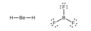
Li, Be, and B can form molecules with less than an octet (< 8 valence electrons) around them. Examples include BeH2 and BF3, both of which are shown in the subsection of OpenStax Section 7.3 called “Electron-deficient Molecules”.
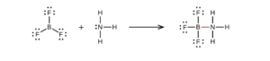
Note from the structure of BF3NH3 in that section that B will happily take an octet if possible
Expanded Octet (more than an octet)
Elements in the third row and below on the periodic table can (not must) form compounds with more than an octet. Once the valence shell is n=3 (3s and 3p orbitals being filled), the 3d orbitals are available if necessary. These compounds are discussed in the subsection of OpenStax Section 7.3 called “Hypervalent Molecules”.
Examples include PCl5 and SF6 (Figure 7.12 of OpenStax):
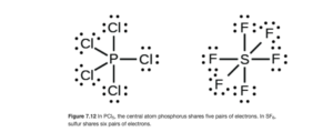
These compounds both exist, but NCl5 and OF6 do not, as N and O (second row elements) cannot have more than an octet.
If there is more than an octet, it is generally on the central atom and can be lone pairs, such as in IF5 and XeF4
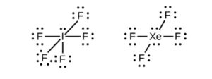
See if you can draw those dot structures using thisprocedure for writing Lewis Dot structures(or another of your preference).
Odd-electron molecules
If a molecule has an odd number of total valence electrons, it is mathematically impossible to give both an octet. Nitrogen monoxide is a stable compound that has 11 total valence electrons (5 from N and 6 from O).
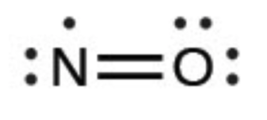
It cannot have a triple bond since that would require one of the atoms to have 9 electrons, which neither N nor O can do. How do we know N has 7? O gets 8 due to its higher electronegativity.
Molecular orbital theory (a bonding theory studied in CHEM 152) describes these molecules better than dot structures.
Objective 11 : Relate bond order to bond length and bond strength.
Bond order is a term to differentiate between single, double, and triple bonds:
- Single bond: Bond order 1
- Double bond: Bond order 2
- Triple bond: Bond order 3
As the number of bonds between two atoms increases, the bond grows shorter and stronger. This table shows the bond lengths and energies for carbon to carbon bonds for the three orders:
| Bond | Bond length | Bond strength |
| C-C (Single) | 1.54 Å | 348 kJ/mol |
| C=C (Double) | 1.34 Å | 614 kJ/mol |
| C C (Triple) | 1.20 Å | 839 kJ/mol |
Bond strength (also known as bond energy of bond enthalpy) is the energy required to break the bond – the higher the value, the stronger the bond.
This single to double to triple trend only works when comparing bonds between like atoms — you can see this in the comparison of C to N bonds (single through triple) and C to O bonds) in OpenStax Table 7.3.
Objective 11 Practice:
Objective 9:Define resonance (delocalized bonding), recognize when resonance can exist and draw all possible resonance forms for a particular compound or ion.
A correct Lewis Dot structure for the carbonate ion has the carbon as the central atom surrounded by three oxygen atoms. Two of the carbon-oxygen bonds are single bonds and one of them is a double bond. The bond lengths and energies of single and double C-O bonds are known (see them on this table). We would expect one of the three bonds to be stronger and shorter than the other two. Experimental data shows that the three bonds are identical , with a bond length and energy of somewhere between that of a single and double C-O bond.
Since there are three bonds that could be drawn as the double while keeping the same dot structure, this situation os addressed by drawing three resonance structures:
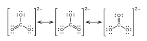
Resonance does NOT mean the molecule “flips” between the resonance positions. CO32- only has one type of bond, with a bond length and energy between that of C-O and C=O. The real structure is the average of the resonance structures. Electrons are delocalized. The electron density can move around the whole molecule. While this seems strange, remember that electrons are as much like waves as they are like little negative particles.
For more detail, see the subsection titled “Resonance” in OpenStax Section 7.4.
Objective 10: Given a table of bond energies, estimate the enthalpy change for a specified reaction.
Bond energy, bond enthalpy or bond strength is defined as the energy required to break the bond, separating the bonded atoms. It is equal to the energy released when forming the bond. Bond energies are tabulated in many places, including in this table available with a periodic table in the unit 3 folder in D2L and Tables 7.2 and 7.3 in OpenStax. The values do vary a bit from source to source, so depenring on the source you use, you may get slightly different results.
Calculating ΔHreaction using bond energies
In the previous unit, you learned how to calculate the heat of reaction (ΔHreaction) using standard heat of formation. Bond energies provide another way to calculate heat of reaction. The values should be close but will not be exactly the same.
This calculation assumes a “path” of breaking all the bonds in the reactant molecules and forming new bonds for the product molecules. Even though that is not the actual path most reactions take, it will provide ΔH since H is a state function. Since it requires energy to break bonds of reactants and it releases energy to form bonds of products:
ΔH = sum B.E. of broken bonds – sum B.E. of formed bonds, or
ΔH = sumB.E. reactant bonds – sumB.E. of product bonds
In OpenStax Section 7.5 (just below Tables 7.2 and 7.3 ) are two step-by-step examples of calculating a heat of reaction using bond energies. Review those, then using that process, see if you can solve this problem:
Calculate ΔH in kJ for the following reaction using average bond energies from this table. :

HINT: you will first need to draw Lewis dot structures to determine the number and types of bonds in each molecule
Assumptions and realities concerning bond energies
Calculations using bond energies assume that all like bonds have the same energy regardless of what molecule they are in. For example, a tabulated value of 413 kJ/mol for C-H assumes all C-H bonds have this energy. In reality, the actual energy of a bond varies with environment. The other bonds and atoms in a molecule affect the bond energy of a specific bond. For example, a C-H bond in CH4 is stronger than the C-H bond in CHF3, because the highly electronegative F atoms pull electron density toward then and away fron the C-H bond, weakening it slightly. Therefore, tabulated bond energies are AVERAGE bond energies and calculated heats of reactions for them are actually just good estimates.
Objective 12 – Relate the number of electron pairs in the valence shell of an atom in a molecule to the geometrical arrangement of the pairs around the atom
Objective 13 – Using Valence Shell Electron Pair Repulsion Theory (VSEPR), predict the geometry of molecules or polyatomic ions
A correct Lewis dot structure show what atoms are bonded to what atoms, show valence electrons, and show the bond order of all bonds. A Lewis dot structure, while correct, does not have to show the actual three dimensional shape of the molecule.
It is useful to know the actual shape or geometry for molecular recognition and chemical behavior. If we do know the Lewis dot structure, we can deduce the actual molecular shape from the dot structure using the VSEPR theory.
Valence Shell Electron Pair Repulsion (VSEPR) theory is based on the idea that valence shell electrons (the electrons shown in Lewis dot structures) will repel each other and will therefore arrange themselves around a central atom in a w degrees.ay to stay as far apart as possible.
Looking at the structure on the left (BeH2), the molecule will be linear as the bonds will stay as far apart as possible, at a 180 degree angle. In the BeF3 molecule on the right, the three bonds will be as far apart as possible at 120 degrees.
Electron “domains” or “regions” in VSEPR
Looking at the structures above, we would say that
- BeH2 has two electron “domains” or “regions” around the central Be atom
- BF3 has three electron “domains” or “regions” around the central B atom
A bond counts as a domain or region. Lone pairs and double or triple bonds also count as domains as they will repel each other as well. If we look at the structure of the nitrite ion (NO2–) below (you can use either resonance structure, it doesn’t matter which)
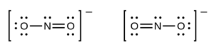
There are three electron regions or domains around the central nitrogen atom:
- the single bond
- the double bond
- the lone pair
(If there is a triple bond in a structure, it counts as one domain as well). These three domains will want to stay as far apart as possible, so they would actually be 120 degrees apart, and the molecule would not be linear as it appears in the dot structure above.
Remember, the dot structure is still correct – it does not have to show the actual three dimensional shape of the molecule. The electron regions or domains are the basis for molecular shape.
Electron Domain (or region) Geometries
Figure 7.16 from OpenStax (shown below) or the VSEPR theory table on D2L (in the Unit 3 Folder) show the electron region geometry (called electron-pair arrangement on the D2L document) for domains or regions ranging from 2 to 6.
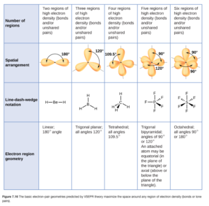
Using either table to look at the molecules we just considered above, we can see that BeH2 (with 2 regions) has a linear electron region geometry (or pair arrangement) while the electron region geometry of BF3 and NO2– is trigonal planar. Note that you have to have the correct dot structure to identify the number of domains and geometry.
Objective 12 Practice
Obtaining Molecular Geometries (Shapes) from Electron Pair Arrangement and Dot Structure
Molecular shape, molecular geometry, and molecular structure is related to, but not the same as, electron region geometry. Molecular shape only describes the location of the atoms. Lone pairs are not part of the description of molecular geometry.
For example, if we look at the structure of NO2–, the electron region geometry is trigonal planar (with angles of 120 degrees.
We would describe the molecular shape as bent, as that would better describe the shape of the arrangement of the three atoms. Even though the lone pair is not included in the description of the molecular shape, it influences it by taking a spot around the central atom.
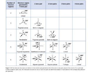
To determine molecular shape, you must consider the number of electron regions and domains and the number of lone (nonbonding) pairs. If there are no lone pairs, molecular geometry is the same as the electron region geometry. If there are lone pairs, the molecular geometry is not the same as the electron region geometry (but is based on it). The VSEPR theory table on D2L or Figure 7.19 in OpenStax (also shown below) shows the shape based on the number of electron regions and lone pairs (you can see bent or angular for NO2– on the table below. If you use the VSEPR theory table on D2L, lone pairs are called “nonbonding domains” on that table.
OpenStax gives good, detailed descriptions of how the various molecular shapes are obtained from the electron pair geometries and several solved examples with good descriptions for determining geometries.
Objective 13 Example
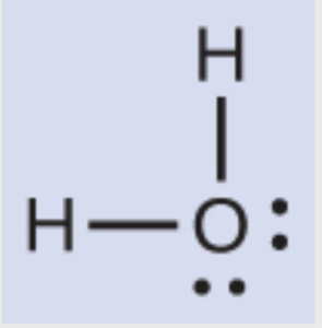
Determine the molecular shape of water.
The first step is to draw a dot structure for water
Number of electron regions: 4
Number of lone pairs (nonbonding domains)
Shape (using the VSEPR theory table on D2L or Figure 7.19 in OpenStax ): bent
Objective 13 Practice
Objective 14: Explain how nonbonding electron pairs compress the angles between bonding pairs.
Lone pairs tend to “spread out”, taking up more room about the central atom. This tends to decreases bond angles in a molecule.
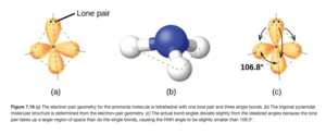
NH3 (ammonia) has the following dot structure:
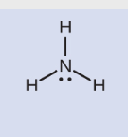
With 4 electron domains, its domain or region geometry is tetrahedral with a 109.5° bond angle. The one lone pair gives it a trigonal pyramid geometry, but we would still expect a 109.5° bond angle. Since the lone pair takes up more room, though (there is no nucleus on the other side attracting those electrons, so the lone pair “spreads out”), the bond angle is squeezed slightly to 106.8°
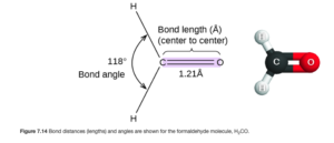
Double and triple bonds repel adjacent electron domains more than electron domains for single bonds do. Therefore, they affect bond angles similarly to lone pairs, taking up more room.
H2CO (shown below – Figure 7.14 from OpenStax) has three electron regions around the carbon, so we would expect three 120° angles, but as is shown in the figure below the H-C-H bond angle is slightly smaller.
Objective 16 -Predict whether or not a molecule has a dipole moment
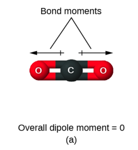
In Objective 5 (see above), you learned about bond polarity. Now we are going to extend that idea to molecular polarity. This idea is easiest to see with three relatively simple molecules, CO2 , OCS, and water.
First, let’s look at CO2. With 2 electron domains and no lone pairs around the central carbon, it is linear. Due to the electronegativity difference between C and O, each C=O bond is polar. But the polarity is equal in opposite directions, so the bond polarities cancel and overall CO2 is not polar.
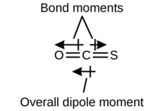
Next, let’s look at OCS. It is also linear, and has the same dot structure except a S atom is substituted for one of the O atoms. Since the C=S bond had a smaller electronegativity difference than the C=O bond, the polarities will not cancel and the molecule will have an overall polarity (as shown by the arrows in the OCS diagram above). This overall polarity is also called an overall dipole moment or net dipole moment.
Finally, let’s look at water. even though both of the O-H bonds have the same electronegativity difference, the geometry of the molecule (bent with 4 electron regions and 2 lone pairs) means that one of the bond polarities goes up and left while the other goes up and right. Even though the left and right portions cancel, there is no bond polarity going down to cancel the one going up, so there is an overall bond polarity or net dipole moment going up. Therefore water has a net dipole moment going up.
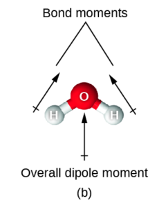
These examples illustrate that for a molecule to be a polar molecule (have a nonzero dipole moment), it must:
–contain at least one polar bond (evaluate the electronegativity difference between atoms in each bond)
–be non-symmetrical (bond polarities will not cancel each other out)
A molecule is not polar when its molecular geometry and electron domain geometry are the same and all the surrounding atoms are identical.
The VSEPR theory table on D2L has a column labeled polarity that summarizes polarity considerations for various molecular shapes. Take a look at that table for the three molecules above (CO2 , OCS, and water). CO2 and OCS are both linear in molecular shape, for which molecules are nonpolar if the terminal atoms are identical For CO2, since they are identical, it is nonpolar. For OCS, it is not. For water, the molecular shape is bent. As the table indicates, bent molecules will always be polar (even if the terminal atoms are identical, the polarities cannot cancel completely as we saw in water above).
Objective 16 practice
Objective 17:Explain the essential features of the hybridization (valence bond) theory.
Objective 18: Explain the concept of hybrid orbitals (sp, sp2, sp3, dsp3, d2sp3) and their relationship to geometrical structures.
Objective 19: Based on the Lewis Dot Structure, describe the hybridization, bonding and geometry about the central atom of an ion or molecule.
Our look at bonding, Lewis dot structures, and VSEPR has all been part of an overall theory of bonding called Valence Bond Theory or the Localized Electron Model. According to this theory, a chemical bond results when orbitals containing valence electrons (shown on dot structures) of the two bonding atoms overlap, allowing sharing of the electrons.
Let’s look at this using CH4 as an example. The valence electrons in carbon are 2s22p2. The valence electrons in each hydrogen is 1s. That means that, according to the theory, bonds should be formed when the four 1s orbitals from the hydrogen atoms overlap with the 2s and 2p orbitals of carbon. The figure below shows two overlaps: the overlap of the 2px (horizontal with two lobes) and 2py (vertical with two lobes) orbitals of carbon with two 1s (blue spheres) orbitals from hydrogens.
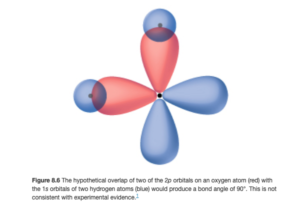
Right away, there is a problem – if the orbitals overlap in this way, the bond angle would be 90°, which disagrees with the actual tetrahedral shape with angles of 109.5° (observed and verified by experiment). This is seen with many covalent molecules – how do you get tetrahedral, trigonal bipyramidal, and other geometries when the orbitals seem to be at right angles from each other all the time? The model that explains this states that when the atoms combine to make molecules, the orbitals (which are just mathematical functions) combine mathematically to make new functions or orbitals that have different shapes and angles – this process is called hybridization and the orbitals are called hybrid orbitals.
Hybridization and hybrid orbitals
The way I like to think of orbitals is “orbitals are like dogs”. Below are pictures of one of my dogs, a corgi-beagle mix:


His ears and face (and bark!) are definitely those of a beagle but the legs (and attitude) are all corgi. The corgi beagle hybrid has characteristics of both.
In CH4 (and other molecules with four electron domains and a tetrahedral electron pair arrangement), the valence s and p orbitaks from the central atom can mix (mathematically) and hybridize much as the corgi and beagle breeds, giving characteristics of both. We can see that in OpenStax Figure 8.15 (shown below)
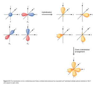
The blue and red orbitals on the upper left are the 2s and the three 2p orbitals of carbon. They combine or “mix” to give four hybrid orbitals (shown in yellow in the upper right portion). The number of hybrid orbitals is the same as the number of orbitals started with. These hybrid orbitals look a little like s (mostly one big orbital) and a little like p (a second lobe — but smaller). The bottom right portion shows they are oriented at a 109.5° angle. If each of these hybrid orbitals overlaps with a hydrogen 1s orbital, you get CH4 with the tetrahedral geometry.
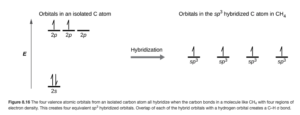
The energy of sp3hybrid orbitals is somewhere between that of unhybridized s and p orbitals, as shown in OpenStax Figure 8.16:
What about lone pairs?
Lone pairs can also fill hybrid orbitals. Water has four electron domains with two lone pairs on the central oxygen. Oxygen will have two of its sp3 hybrid orbitals filled with two electrons, while the other two hybrids have one electron, enabling it to form two bonds with hydrogens.
Therefore, hybridization is determined by the total number of electron regions or domains, not the number of bonds with other atoms. Four regions around a central atom means sp3 hybridization.
Other hybridizations
As you just learned, hybridization is determined by the total number of electron regions or domains. Hybridizations for 2-6 electron domains are listed below:
| Electron regions or domains | Hybridization |
| 2 | sp |
| 3 | sp2 |
| 4 | sp3 |
| 5 | sp3d or dsp3 |
| 6 | sp3d2 or d2sp3 |
The VSEPR theory table on D2L also has these hybridizations listed. Remember, the hybridization lists the number and types of orbitals being mixed or hybridized, so sp means one s and one p, while d2sp3 means two d, one s, and three p for a total of six.
Descriptions of hybridizations other than sp3, in addition to pictures of the hybrid orbitals, are in OpenStax Section 8.2.
Objective 17-19 Practice
Objective 15: Using dot structures, determine the number of sigma and/or pi bonds in a molecule or polyatomic ion given the chemical formula.
Sigma bonds
All of the bonds that we examined in the sp3 hybridized bonds are sigma (σ) bonds. In a sigma bond, the orbitals bond head-to head and the electron density is concentrated along the line connecting the nuclei (internuclear axis). OpenStax Figure 8.4 illustrates sigma bonding.
The small black dots represent nuclei and the red ad blue areas are orbitals.
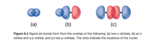
All single bonds are sigma bonds.
Pi bonds
In a pi (π) bond , the orbitals overlap side to side. As can be seen in the figure below (OpenStax Figure 8.5), the orbital overlap and electron density is above and below the internuclear axis.
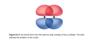
π bonds occur between p orbitals (pi is the Greek p) that are not involved in the hybridization.
A double bond consists of one sigma and one pi bond, and a triple bond consists of one sigma and two pi bonds.
Example 8.1 in OpenStax gives a good example of counting σ and π bonds in a molecule.
Objective 15 practice
How pi bonds work in double bonds
The ethylene molecule (C2H4) has the following dot structure:
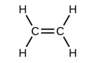
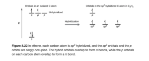
each carbon atom has a hybridization of sp2 (three electron domains around each). In sp2 hybridization, one of carbons p orbitals is left out of the hybridization (and is called an unhybridized p orbital). This is shown in an orbital diagram in Figure 8.22 of OpenStax (see below)
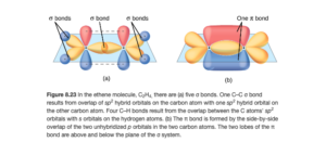
The sp2 hybrid (yellow) and unhybridized p (red and blue) carbon orbitals are shown below (Figure 8.23 OpenStax). The double C=C bond is seen to consist of a sigma bond between two sp2 hybrid orbitals and the pi bond between the unhybridized p orbitals.
Objective 20 –Explain the concept of delocalization in pi bonds.
Earlier, you learned about the concept of resonance using the carbonate ion (CO32-).
In resonance structures, the real structure is the average of the resonance structures. The pi bond which makes the single a double bond has to be drawn somewhere — but in reality, the pi bond is shared equally by all three C-O bonds. Each of the four atoms in the carbonate ion has a p orbital. The p orbitals on all three oxygens overlap with the p orbital on the central carbon. This means the π electrons are not localized between the nitrogen and one of the oxygens, but rather are delocalized throughout the ion. How is this possible? Again, remember electrons are as much like waves as they are particles.