Introduction
The transition metals are the elements in the d block of the periodic table. There are also two subgroups called inner transition elements where the f orbitals are being filled — the lanthanides and the actinides. We will focus on the d-block elements.
The electron configurations of the transition metals include partially filled d orbitals. These outermost d electrons are “inner” electrons. For example, even though the 3d electrons are added after the 4s they have a reasonable probability of being closer to the nucleus at times than the 4s. Therefore, they do not participate in bonding as well as valence s and p orbitals.
As a result, the column chemical behavior is less strong in transition metals than in Groups I-VIIIA. Rows (periods) in periodic table act similarly as well as columns (groups)
An important group of compounds involving transition metals is known as metal complexes or coordination compounds. We will take a close look of those in this unit. Transition metals and their compounds also exhibit interesting magnetic properties and vibrant colors – we will look at reasons for these properties as well.
Objective 3: Write electron configurations for transition metal atoms and metal ions.
Many transition metals exhibit more than one oxidation state (you have seen this). Some examples that should be familiar from your study of chemistry to this point include:
- Copper forms Cu+ and Cu2+ ions.
- Iron forms Fe2+ and Fe3+ ions.
There are many other examples – Figure 19.4 in OpenStax shows oxidation states observed in the first row transition metals. Note that the +2 oxidation state is observed in most of the transition metals — this is due to loss of the outermost s electrons. Oxidation numbers greater than 2 are due to the loss of the outermost “d” electrons in addition to the “s” electrons.
Electron Configurations of Transition Metal Ions
In transition metal atoms, for ground state clectron configurations, ns orbitals are filled before (n-1)d orbitals. In other words, 4s are filled before 3d, 5s are filled before 4d, etc. For example, the electron configuration for manganese (Mn) is:
1s22s22p63s23p64s23d5 0r [Ar]4s2 3d5
But when oxidized, transition metals lose their outer “s” electrons before they lose their “d” electrons. For manganese, that means it will lose the 4s before the 3d. To form the Mn2+ ion, a manganese atom loses two electrons>. The electron configuration will be:
Mn2+ : 1s22s22p63s23p63d5 0r [Ar]3d5. The configuration using the [Ar] for the core electrons is called the shorthand or condensed electron configuration.
When manganese loses four electrons to form Mn4+, is will lose 3d after losing the 4s:
Mn4+ : 1s22s22p63s23p63d3 0r [Ar]3d3
Objective 3 Practice
Objective 1: Define, explain and/or give an example of the following: central ion (transition metal ion), metal complexes, complex ion, ligand, coordination sphere, coordination number, geometry
Objective 2: Describe the structure of coordination compounds including: the central atom, ligands, metal complex, coordination number, geometry, and oxidation number.
Before we look at coordination compounds, let’s briefly review a type of compound you have seen before: an ionic compound. We’ll use calcium carbonate (CaCl2) as an example.
Calcium chloride is an ionic compound made of calcium cations (Ca2+) and chloride anions (Cl–). A 1:2 ratio is required to balance the charges for a neutral compound. Remember, ionic compounds do not exist as molecules, so there is not calcium chloride molecules with one calcium and two chlorine atoms; rather it exists as a crystal lattice, a repeating structure with a 1:2 ratio of calcium to chloride ions.
Coordination Compounds
Coordination compounds are also ionic compounds, like our calcium chloride example. Let’s look at one:
[Co(NH3)5Br]Cl2 is an example of a coordination compound. Like calcium chloride, it
- is an ionic compound made up of cations, [Co(NH3)5Br]2+, and chloride anions, Cl–
- has a 1:2 ratio of cation to anion to balance the charges for a neutral compound.
- exists as a crystal lattice, a repeating structure with a 1:2 ratio of cations to chloride anions.
The only difference is the cation — instead of Ca2+, this compound contains, [Co(NH3)5Br]2+, which is a complex cation. These complexes (or metal complexes) are in square brackets. They can be cations, anions, or neutral compounds. In this example compound, the complex is a cation. The complex consists of a central metal ion surrounded by ligands.
If the complex ion is accompanied by a non-complex ion to make a neutral compound, the non-complex ion is called a counter ion. In [Co(NH3)5Br]Cl2 , Cl– is a counter ion.
Let’s take a closer look at the complex. The complex (a cation in our example) consists of a central metal ion surrounded by ligands.
- The central metal ion is Co3+. Central metal ions are typically transition metals. You should be able to determine the charge from the coordination compounds formula (we will practice this later).
- The ligands are NH3 and Br-1. Ligands are Lewis Bases (electron pair donors) that bond to the transition metal ion using the lone pair. The resulting bond is called a coordinate covalent bond.
Ligands
Ligands are the molecules or ions that bond to the metal in a complex. They are Lewis Bases (electron pair donor) that bond to the transition metal ion using the lone pair. The atom of the ligand that supplies the lone pair electrons for the metal-ligand bond is the donor atom. Let’s look at how the ligands bond to the central ion in our complex ion example:
Ligands can be neutral such as water or ammonia:
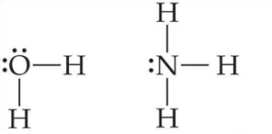
Ligands can also be ions such as chloride or cyanide:

In the following practice questions, can you identify the donor atoms in each of the ligands above?
Geometry of Coordination Complexes
Geometry can be defined as the arrangement of donor atoms of the ligands around the central metal ion. The coordination number is the number of bonds between transition metal ions and ligands in a complex. We will concentrate on coordination complexes with coordination numbers 4 and 6. The geometries we will focus on should be familiar to you from your study of VSEPR theory in your first semester general chemistry class.
Geometries with Coordination Number 4
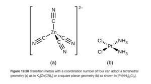
Two geometries are observed in coordination compounds with a coordination number of 4. These are tetrahedral, a three-dimensional geometry in which all four bonds with ligands are equally spaced around the central atom with a bond angle of 109.5°, and square planar, a flat, two dimensional geometry in which all four bonds with ligands are equally spaced around the central atom with a bond angle of 90°. Figure 7.19 in OpenStax illustrates the tetrahedral and square planar shapes (think of the “E” as the central transition metal ion and the “X” as the donor atom of the ligand).
Of these two geometries, tetrahedral is the most common. Square planar is characteristic of transition metals with eight d electrons in the valence shell – examples include Pt2+ and Au3+. Make sure you understand (using the electron configuration material from Objective 1) why these ions have eight d electrons in the valence shell. You will not be expected to predict whether a complex will be tetrahedral or square planar.
Examples of complexes with coordination number four include:
- [Zn(CN)4]2- (tetrahedral) – OpenStax Figure 19.20a
- [PtCl2(NH3)4] (square planar) – OpenStax Figure 19.20b
Geometry with Coordination Number 6
Coordination compounds with a coordination number of 6 have octahedral geometry. Figure 7.19 in OpenStax illustrates the octahedral and shape, in which the six bonds with ligands are spaced at 90° angles around the central metal atom on perpendicular x,y,and z axes. Figure 19.19 in OpenStax shows three examples of octahedral complexes.
An example of a complex with coordination number six:
[Co(H2O)6]Cl2 The drawing of this is shown as the drawing on the left of Figure 19.19 . Notice only the six water ligands determine the geometry. The two Cl– ions are counter ions and are outside the square brackets in the formula.
While four and six are the most common coordination numbers (and the ones we will focus out attention on), coordination numbers from 2 to 9 or even more have been observed. Table 19.5 in OpenStax shows the geometry and examples for these coordination numbers. Take a look at the formulas in the tables and see if you can understand how the formulas show you the coordination numbers. If that is confusing to you, it will be discussed in a later objective. If it is still confusing, contact me.
Monodentate and Polydentate Ligands
Monodentate ligands are ligands that have a single donor atom. The prefix “mono” means one and the term “dentate” is related to dental or dentist, which is associated with teeth. So monodentate means “One Tooth” to hold onto or bond to the transition metal central atom.
Water and ammonia are examples of monodentate ligands:
List of Common Monodentate Ligands
A list of common monodentate ligands is in the table below.
- The names are there for your reference – you are not expected to know them and we will not cover coordination compound nomenclature.
- You are expected to recognize the formulas as monodentate ligands and recognize where they are in coordination compound formulas.
- The charges on the ligands are important. You will need to take the charges of the ligands into account in order to determine the oxidation state of the transition metal — which as you will see will be necessary
| Formula | Name |
| H2O | aqua |
| NH3 | ammine |
| CH3NH2 | methylamine |
| CO | carbonyl |
| NO | nitrosyl |
| NO21- | nitro |
| ONO1- | nitrito |
| Cl1- | chloro |
| F1- | fluoro |
| Br1- | bromo |
| I1- | iodo |
| CN1- | cyano |
| SCN1- | thiocyano |
| OH1- | hydroxo |
| O2- | oxo |
Polydentate ligands have two or more donor atoms that can coordinate to a metal ion, occupying multiple coordination sites. They are also called chelating ligands.
Ethylenediamine is a bidentate (“two teeth”) ligand, with two donor atoms.
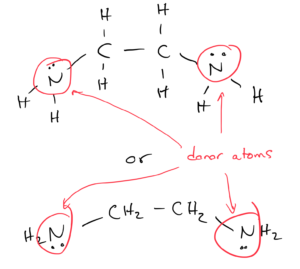
The two nitrogen donor atoms are spaced far enough apart in the molecule that an ethylenediamine ligand can form two bonds with the transition metal while still keeping the geometry of the complex. For example, three ethylenediamine molecules can form an octrahedral complex with chromium (the coordination number is still 6). The middle figure in OpenStax Figure 19.19 shows this complex.
Since polydentate ligands can be quite large (with complicated, long formulas) abbreviations are used in their formulas. For example, the abbreviation for ethylenediamine is (en). Using this, the formula for the middle figure in OpenStax Figure 19.19 is:
[Cr(en)3](NO3)3
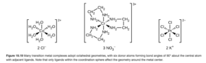
Notice the three (en) give a coordination number of 6 since (en) is bidentate. Also notice the three nitrate ions are counter ions.
You should also recognize oxalate (C2O42-) and carbonate (CO32-) are bidentate ligands.
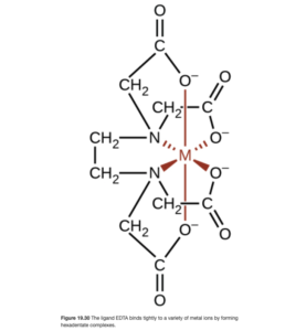
EDTA – a hexadentate ligand
Ethylenediaminetetraacetic acid (EDTA) is an important hexadentate (six teeth!) ligand. With its four oxygen and two nitrogen donor atoms and very long chain structure, it can wrap around (or chelate) most common metal ions all by itself. A picture of the resulting complex is shown in OpenStax Figure 19.30. The formula for this complex would be [M(EDTA)] where M is the transition metal.
If you took CHEM 161 lab at LCC, you may recall a lab in which water hardness (Ca2+ and Mg2+) levels were determined by titration with EDTA. In that titration, Ca2+ was complexed by EDTA to form [Ca(EDTA)]2+.
Coordination Compound Formulas
Using the formula [Co(NH3)5Br]Cl2 as an example, let’s take a closer look at eh formula to see what information these formulas give us.
The complex ion is the formula in the square bracket. The complex ion in our example is a cation: [Co(NH3)5Br]+2. We can tell it is a cation as it is on the left side of the overall formula. A complex ion that is an anion would be on the right side of the overall formula – for example Na2[PtCl4]. Complexes can also be neutral. If they are, there is no counter ion. An example is [Cr(C2O4)3].
You should be able to identify the complex ion and its charge.
The transition metal ion comes first in the complex ion part of the formula (in this example: Co3+). How is the oxidation state of +3 determined? Starting with the overall formula [Co(NH3)5Br]Cl2, the complex ion [Co(NH3)5Br]+2 has a +2 charge since it is associated with two chloride counter ions. Within [Co(NH3)5Br]+2, the NH3 ligands are all neutral and the Br– ligand has an oxidation state of -1 (see the table of monodentate ligands from the previous objective). Therefore, by difference, Co must have an oxidation state of +3.
You should be able to identify the transition metal ion and its oxidation state.
The ligands come after the transition metal ion in the complex ion part of the formula. The ligands are NH3 (5 of them) and Br– (1 of them). Since there are six ligands, and they are all monodentate, the coordination number is 6 and the geometry is octahedral. You should be able to identify the ligands, and from the number of type of ligands determine the coordination number.
Also, note that there are 5 NH3 ligands. The ligand is NOT “(NH3)5“. (NH3)5 would imply the 5 ammonias are bonded together, which they are not.
Coordination Sphere
The “coordination sphere” contains the central atom and the ligands. In our example:
- Co3+, NH3 (5 of them) and Br– (1 of them) are in the coordination sphere
- The Cl– counter ions are not part of the coordination sphere
Objective 1 and 2 Practice
For the coordination complex formula [Co(NH3)2(en)2]Cl2 , answer the following questions:
For the coordination complex formula (NH4)2[Fe(H2O)2Br4] , answer the following questions:
Answer the following:
Objective 4:Define isomerism and give an example.
Objective 5:Distinguish between structural isomerism and stereoisomerism. (note: Optical isomerism is NOT covered)
Objective 6: Identify and draw structures for the following types of isomerism: structural, stereoisomers, coordination sphere, linkage and geometric.
Isomerism in coordination compounds
Isomers are compounds that contain the same numbers of the same atoms (sometimes stated as “same formula” but have different properties. Isomers are seen in many areas of chemistry – coordination chemistry is just one of them.
There are two general types of isomerism in coordination chemistry : structural isomers and stereoisomers. Structural isomers have different bonds. The atoms bond in different arrangements in structural isomers. In stereoisomers, the bonding is the same: the same atoms are bonded to the same atoms. But in stereoisomers, the spatial arrangements of the atoms can be different. We will look at each next.
Structural isomerism
Structural isomers have different bonds. Different atoms bond to different atoms in structural isomers (even though the overall compounds have the same overall numbers of the same atoms). The atoms bond in different arrangements in structural isomers. In coordination chemistry, there are two types of structural isomerism: coordination isomerism and linkage isomerism.
Coordination Isomerism
Coordination isomers differ in what ligands are bonded to the metal and what is outside the coordination sphere. It is most easily seen in examples:
[Fe(H2O)5Br]Cl and [Fe(H2O)5Cl]Br
In the first isomer, bromide is a ligand and chloride is a counter ion. In the second isomer, these are switched, making chloride the ligand and bromide the counter ion
[Cr(H2O)6]Cl3, [Cr(H2O)5Cl]Cl2 ∙ H2O, and [Cr(H2O)4Cl2]Cl ∙ 2 H2O
In this example, chloride can be either a ligand or a counter ion, and water can be either a ligand (directly bonded to the transition metal) or a water of hydration (loosely bound in the crystal). The isomers have different combinations.
Linkage Isomerism
Linkage isomers have the same complex ion and ligands but the point of attachment (donor atom) of at least one of the ligands differs. For example, [Zn(CN)I3]2- has the following linkage isomers:
![Linkage isomers of the complex [Zn(CN)I3]2- are shown. Both isomers have three iodide ligands and one cyanide ligand bonded to the central zinc atom. In one linkage isomer, the carbon atonm of the cyanide is bonded to the zinc. In the other, the cyanide bonds to the zinc through the nitrogen atom.](http://fe2.openlcc.net/chem152/files/2020/10/Linkage-isomer-287x300.png)
In one isomer, the carbon of cyanide serves as the donor atom. In the other, the nitrogen serves as the donor atom, bonding to the Zn.
The following ligands are capable of linkage isomerism:


As an example, the last one listed is the thiocyanate ion, SCN–. Either the sulfur or nitrogen can serve as a donor atom and bond with the transition metal. The carbon cannot. In complex ion nomenclature, these isomers are differnetiated by the thiocyanato and isothiocyanato nomenclature. You are not responsible for knowing these names as we are not covering coordination complex nomenclature.
Stereoisomerism
In stereoisomerism, the bonding is the same: the same atoms are bonded to the same atoms. But the spatial arrangements of the atoms is different. Two common types of stereoisomerism are geometric isomerism and optical isomerism. We will not study optical isomerism in CHEM 152, but it will be very important in organic chemistry.
Geometric isomerism
The type of geometric isomerism we will examine is cis-trans isomerism. In cis isomers, like items are spaced adjacent to each other while in trans isomers like items are opposite.
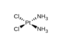
Square planar cis-trans isomerism
We are going to examine cis-trans isomerism in the [Pt(NH3)2Cl2] complex. If you look at Figure 19.20b below from OpenStax, you can see this square planar complex. Thus would be the cis isomer as the two Cl are adjacent and the two ammonias are adjacent.
The trans isomer of [Pt(NH3)2Cl2] is shown below:
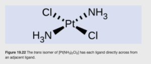
Note the two Cl ligands are opposite from each other (as are the ammonias).
Tetrahedral cis-trans isomerism
There is not cis-trans isomerism in tetrahedral complexes as all ligands are adjacent to the other three with a 109.5 degree bond angle
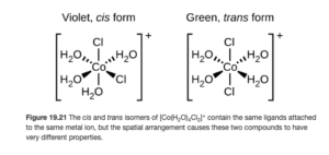
Octahedral cis-trans isomerism
The cis-trans isomers of the octahedral [Co(NH3)4Cl2]+ complex ion are shown below. (Figure 19.21 OpenStax)
Objective 4-6 practice
Objective 7: State the basic assumptions of the crystal field model.
Objective 8: Explain how the electrostatic interaction between the ligand and the metal’s d-orbitals in an octahedral field results in the splitting of the energy levels.
Crystal Field Theory (Bonding in Coordination Compounds)
In transition metals, the d orbitals are partially filled. In a free or uncomplexed transition metal ion (no ligands are bonded to it), all 5 of the nd orbitals (whether 3d,4d,5d, etc) are equal in energy.
However, when ligands bond to the transition metal ion by donating their lone pairs, the ligand’s lone pairs (remember, ligands are Lewis bases and donate an electron pair) will repel the transition metal’s d electrons. Not all of the d orbitals are repelled equally, causing some of the d orbitals in complexed transition metals to be higher in energy than others. The difference in energy between the transition metal ion’s d orbitals caused by the ligands is called the crystal field splitting. As we will see, crystal field theory explains color and magnetism of complexed ions.
The following are points or postulates in the crystal field theory:
- It is assumed the metal – ligand bonds are ionic
- Bonds form due to the attraction of the electrons on the ligand for the charge on the metal cation
- The ligands are treated as “negative point charges”
- Electrons on the ligands repel electrons in the d orbitals of the metal ion, affecting the energies of the metal ion’s d orbitals
- The geometry (tetrahedral, octahedral, etc.) of the complex ion must be considered. In different geometries, the ligands approach the transition metals at different angles, affecting the transition metal d orbitals differently.
Crystal Field Splitting in Octahedral Complexes
In a free, uncomplexed ion, all of the d orbitals have the same energy.
Here are drawings of the 3d orbitals (OpenStax Figure 19.33)
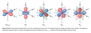
In an octahedral crystal field, the ligands approach along x,y,z, axes with their lone pairs, which interact with the metal’s d electrons.
The two d orbitals on the left (dz2 and dx2–y2) above lie directly on the x,y, and z axes, meaning the ligands approach directly toward these orbitals. Electrons in these orbitals face greater repulsion.
The three orbitals on the right (dxy, dyz, and dxz orbitals) have lobes that lie between the axes, meaning the ligands approach between these orbitals. Electrons in these orbitals face less repulsion.
As a result, in an octahedral crystal field, the complexed ion d orbitals with higher repulsion have higher energy than d orbitals with lower repulsion.
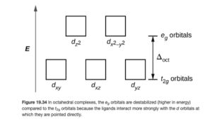
Energies of d orbitals in an Octahedral Crystal Field
Figure 19.34 in OpenStax (also shown below) illustrates the effect of these different repulsions between orbitals and ligands. Since the dz2 and dx2–y2 orbitals face greater repulsion from the ligands, they are now higher in energy than the dxy, dyz, and dxz orbitals. The difference in their energies is represented by the symbol Δ. Δ is called the crystal field splitting energy.
Objective 10: Draw d-orbital splitting diagrams for octahedral and tetrahedral complexes.
The video below will walk through the steps required to draw a filled d orbital diagram for chromium in [Cr(H2O)6]3+
Objective 9: Explain the splitting of the energy levels in a tetrahedral complex and the reason for the smaller crystal field splitting compared to the octahedral complexes.
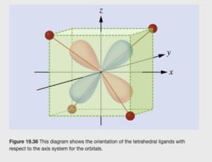
To draw a d orbital diagram for a tetrahedral complex such as [Zn(CN)4]2-, you would follow a similar process to that in the video above, with one important difference. In a tetrahedral complex, the ligands approach and bond at 109.5°angles, and none of them point directly at any of the transition metal’s 3d orbitals, as shown in OpenStax Figure 19.36:
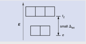
This leads to two differences between tetrahedral and octahedral crystal field splitting:
First, the splitting is opposite. Two orbitals are lower in energy than the other three. Secondly, the Δ is smaller. For the same transition metal and the same ligands, the tetrahedral crystal field splitting is 4/9 (44%) of what it would be in an octahedral field.
Objective 11: Distinguish between high and low spin complexes and strong and weak field octahedral complexes.
To look at this objective, let’s start by drawing a filled d orbital diagram for cobalt in [Fe(CN)6]4-:
Since the overall charge on the complex ion is -4, and there are six cyanide (CN–) ligands, the oxidation state on Fe is +2.
Electron configuration of Fe2+: [Ar]3d6 so it will be d6.
There are two different ways we can place the six electrons into the octahedral splitting diagram See OpenStax Figure 19.35):
![A diagram is shown with a vertical arrow pointing upward along the height of the diagram at its left side. This arrow is labeled, “E.” to the right of this arrow are several rows of squares outlined in yellow. The first row has three linked squares at the lower right side of the diagram labeled, “[ F e ( C N ) subscript 6 ] superscript 4 negative sign.” Each square contains two half arrows, with the left half arrow pointing up and the right half arrow pointing down. A second row is positioned just above and to the left of the first, with the bottom of the squares at a height equal with the top of the squares in the first row. This group is also composed of 3 linked squares. The square to the left contains two half arrows, with the left half arrow pointing up and the right half arrow pointing down. The remaining two squares in this row only have upward pointing half arrows. At the bottom of the figure, just below this group is the label “[ F e ( H subscript 2 O ) subscript 6] superscript 2 plus sign.” To the left of this row, a third row that includes 5 linked squares is positioned with the lower edge of the squares at a height equal to the tops of the squares in row two. The square to the left contains two half arrows, one up and one down. All other squares in this group contain single upward pointing arrows. At the bottom of the figure beneath this row appears the label, “F e superscript 2 plus sign no ligands.” A fourth row composed of 2 linked squares appears to the right and above the second row. The lower edge of the squares is at a height level with the top of the squares of the third row. Each of these squares contains a single upward pointing half arrow. A fifth row of 2 squares is positioned above and to the right directly above the first row with the base of the squares positioned at a level equal to the top of the previous row of squares. These squares are empty. At the right of the diagram, a short horizontal line segment is drawn just right of the lower side of the rightmost square of the first row. A double-headed arrow extends from this line segment to a second horizontal line segment directly above the first and right of the lower side of the fifth row of squares. The arrow is labeled, “Low spin, large delta subscript oct,” to the right. The lower horizontal line segment is similarly labeled, “t subscript 2 g,” and the upper line segment is labeled, “e subscript g.” To the right of the second and fourth rows, a short horizontal line segment is drawn just right of the lower side of the rightmost square of the second row. A double-headed arrow extends from this line segment to a second horizontal line segment directly above the first and right of the lower side of the fourth row of squares. The arrow is labeled, “High spin, small capital delta subscript oct,” to the right. The lower horizontal line segment is similarly labeled, “t subscript 2 g,” and the upper line segment is labeled, “e subscript g.”](http://fe2.openlcc.net/chem152/files/2024/03/Fig-19.35-OpenStax-300x139.png)
In the diagram on the right, the three lower energy orbitals fill before any electrons are put into the upper two. This occurs if the Δ is large. If the Δ is sufficiently large, it is energetically favorable to pair electrons in the orbitals (despite increased repulsion due to having two electrons in the same orbital). This is called the strong field splitting.
In the diagram in the middle, the upper two orbitals get one electron before any of the orbitals get a pair of electrons. This occurs if the Δ is small. If the Δ is sufficiently small, it is energetically favorable to put electrons in the (slightly) higher energy orbitals rather than pair electrons in the orbitals (there is increased repulsion due to having two electrons in the same orbital). This is called the weak field splitting.
High and low spin
High spin is simply another name for weak field and low spin is simply another name for strong field. The names come from the total of the ms (+1/2 or -1/2) quantum numbers of the electrons. If you add the ms values of the high spin configuration, you will get a higher absolute value for total spin than you will if you add the ms values of the low spin configuration, as more spins cancel in the low spin configuration.
What determines high vs and low spin
The magnitude of Δ depends on both the ligand and the transition metal. For the same transition metal ion (Fe2+ in our example) it turns out that with six cyanides as the ligand, the splitting is large enough to result in a strong field (low spin) complex (see figure on right. Six waters as ligands results in a smaller splitting , so [Fe(H2O)6]2+ is a weak field (high spin) complex. You will not be expected whether a particular complex will be high or low spin, but given a spectrochemical series (coming up next), you should be able to predict which complexes might more likely be high or low spin.
Objective 13: Explain the significance of the spectrochemical series.
Objective 14: Given a spectrochemical series, predict whether a complex ion is more likely to have weak or strong crystal field splitting.
The magnitude of the energy gap, Δ, depends on both the metal and surrounding ligands. In a spectrochemical series, ligands can be placed into a sequence in order of increasing energy gap Δ.
Spectrochemical series (listed from smaller splitting (Δ) to larger Δ).
- I1-
- Br1-
- Cl1-
- F1-
- OH1-
- H2O
- NH3
- en
- NO2 1-
- CN1-
You should be able to apply this spectrochemical series (or a smaller one) if given. There will be practice on this below.
Objective 13-14 practice
Using the spectrochemical series above, answer the following question:
What d electron configurations exhibit both high and low spin in octahedral complexes?
Objective 17: Explain how crystal field theory can be used to predict whether a complex is diamagnetic or paramagnetic.
Objective 18: Predict the number of unpaired electrons in a high and low spin octahedral complex and determine if that complex is diamagnetic or paramagnetic.
Many transition metals have significant magnetic properties. In diamagnetic atoms and ions, all electron spins are paired. Therefore, there is no net magnetic moment.
In paramagnetic atoms and ions, there are unpaired spins. The magnetic fields are randomly arranged, though, unless placed in an external magnetic field.
By looking at the filled d orbital diagram you can determine whether a complex is paramagnetic or diamagnetic. If all d orbitals are empty or fully filled (no unpaired spins) it is diamagnetic. If at least one d orbital is half filled with only 1 electron, it is paramagnetic.
In the drawing below, both the uncomplexed Fe2+ ion and the high spin Fe2+ ion in an octahedral complex (see drawing in objective 11) are paramagnetic, due to the four unpaired electrons it only takes one). The low spin complex is diamagnetic.
Objective 17-18 Practice
Objective 12: Explain the origin of color in complexes using d-orbital splitting.
Objective 15: Explain how the colors of substances are related to their absorption and reflection of incident light.
Crystal Field Theory & Color
In most transition metal octahedral complexes, the energy difference due to crystal field splitting (Δ) corresponds to energies of photons in the visible region of the spectrum. Energy is related to frequency and wavelength by the equations:

where:
- E is energy
- h is Planck’s constant
- c is the speed of electromagnetic radiation
is frequency
is wavelength
When atoms or molecules absorb light at the proper frequency or wavelength, electrons are excited from lower energy to higher energy orbitals. Conversely, if there are higher energy unfilled orbitals available, an atom or molecule can absorb light at the frequency or wavelength corresponding to the energy differenct between the initial and final state. If the crystal field splitting results in energy differences that correspond to visible wavelengths, visible light can be absorbed by complex and color will be observed. The color observed depends on the colors absorbed – the human eye will see the complementary color of the color absorbed (see OpenStax Figure 19.37).
Complex ions with d0 configuration (no electrons in outer d orbitals) or d10 configuration (outer d orbitals completely filled) are generally colorless. In the case of d0 , electron transfer cannot occur between the vacant d orbitals. For example, complex ions of Sc3+ are colorless.
For d10 , there is no available space for the electron to be excited to, so these are also are colorless. Cd2+ and Zn2+complexes are notable examples.
Color and the spectrochemical series
Some ligands tend to make the gap between d orbitals larger, some tend to make it smaller, due to their position on the spectrochemical series and the different resulting crystal field splittings. When the energy gaps are different, the frequency or wavelength of light absorbed (due to 
Objective 15 practice
Consider the following coordination compounds:
- K3[CoCl6]
- [Co(H2O)6]Cl3
- [Co(NH3)6]Cl3
- K3 [Co(CN)6 ]
Use the spectrochemical series: Cl–<H2O<NH3<CN– (where Cl– has the smallest crystal field splitting and CN– has the largest splitting) to answer the following questions:
Tetrahedral crystal field splitting
As we saw in Objective 9, tetrahedral complexes have a smaller crystal field splitting that is the opposite of that seen in octahedral complexes
Due to the smaller splitting, these complexes are always weak field (high spin). Also, the smaller Δ usually corresponds to IR radiation, so visible light not absorbed and the wide varieties of colors seen in octahedral complexes are not observed.
Tetrahedral crystal field theory practice
Draw a filled d orbital diagram for iron in [FeCl4]2-, then use it to answer the questions below: