Electrochemistry is the study of redox reactions that produce or require an electric current.
You should start with a review of the redox material from the last unit – it is essential to the study of electrochemistry. The four objectives listed below are necessary to start your study of electrochemistry, so you should review the Bruce’s Notes on Oxidation-Reduction as well as any other material that would help you. In your review of the Bruce’s notes, you can skip over Objective 7 (balancing redox reactions) and Objective 5 (single replacement reactions).
Objective 1: Define and identify oxidation and reduction – Review
Objective 2: oxidation-reduction (redox) reactions – Review
Objective 3: Assign oxidation states to the elements in a compound or ion. – Review
Objective 4: Identify oxidizing and reducing agents. – Review
Objective 1-4 Practice
Consider the following redox reaction:

It can be broken into the following half reactions:


Answer the following questions:
Objective 5: Diagram and describe and explain voltaic (or galvanic) and electrolytic cells: indicate the cathode, anode, salt bridge, direction of flow of electrons, direction of migration of ions and the half-cell reaction involved at each electrode.
Let’s again consider the redox reaction from the practice questions above:
It can be broken into the following half reactions:
In this reaction (like any redox reaction) electrons are transferred. This electron transfer (and reaction) would occur if the MnO4–, Fe2+ , and acid are mixed in solution in a beaker, flask and other container. Normally, this is how we would think of it. This electron transfer (and reaction) would occur if the MnO4–and Fe2+ are separated physically (in the necessary acidic solution) but the electrons are allowed to flow through an electric wire. This means of carrying out the reaction (without direct physical contact of the reactants) is an electrochemical cell.
Electrochemical cells – two types
In galvanic cells (also called voltaic cells), chemical energy is converted to electrical energy, producing an electric current. Electric current is used to do work on the surroundings. A galvanic cell uses a spontaneous redox reaction (ΔG < 0) to generate electricity. Galvanic (or voltaic) cells also have a positive voltage (cell potential).
In electrolytic cells, electrical energy is used to produce a chemical change. The surroundings does work on the system. These cells are used to drive a nonspontaneous redox process (ΔG > 0) to occur. Electrolytic cells have a negative voltage (cell potential).
Note that cell potential and free energy change (ΔG) are always opposite in sign. We will discuss the definition and concept of cell potential at length in later objectives.
Galvanic or Voltaic Electrochemical Cells
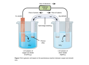
The figure below (Figure 17.3 from OpenStax) is a schematic of a galvanic cell.
Electrodes in the Voltaic Cell
The electrodes provide a solid surfaces(metal) for electron transfer to occur on in the two compartments. If there is no metal involved in the chemical reaction, an inert solid (usually platinum or graphite) electrode is used. This cell consists of two electrodes (copper and silver) each in solution. The copper electrode is in a solution of Cu2+ ions (provided by copper(II)nitrate) and the silver is in a solution of Ag+ ions (provided by silver nitrate). The electrodes are connected electrically in a circuit, and electrons flow spontaneously from the copper to the silver electrode (we will go over how we know this later).
The copper electrode is the anode in this cell. The anode is the electrode where oxidation occurs. Since oxidation is the loss of electrons, electrons leave the anode.
The silver electrode is the cathode in this cell. The is the electrode where reduction occurs. Since reduction is the gain of electrons, electrons flow to the anode.
In all electrochemical cells (whether voltaic or electrolytic), since oxidation occurs at the anode and reduction occurs at the cathode, electrons always flow from the anode to the cathode.
Half reactions and overall redox reactions in the voltaic cell
Half reaction at the anode (oxidation)
Half reaction at the cathode (reduction)
Overall redox reaction

The Salt Bridge
The salt bridge is a porous glass disc or a U-tube filled with an electrolyte separating the two compartments. Examples include salts like KCl, or in the diagram for this example, NaNO3.
In the above cell, electrons are flowing left to right from the copper to the silver electrode. As that occurs, negative charge will begin to build up on the right side, eventually stopping electron flow. The salt bridge allows ion flow to compensate for the electron flow so the excess negative charge doesn’t build up on the right, allowing the reaction to continue. As you can see, the Na+ cations flow through the salt bridge in the same direction as the electrons, while the NO3– anions flow in the opposite direction.
Cations in the salt bridge always move towards the cathode to neutralize the excess of negatively charged ions.
Anions in the salt bridge always move towards the anode to neutralize the excess cations formed by oxidation.
Positive and negative electrodes in voltaic cell
By convention, one electrode in an electochemical cell is labelled positive and the other negative. In a voltaic cell, the anode is labeled negative and cathode is labeled positive. Electron flow is anode to cathode, so in a voltaic cell electrons flow from the negative to positive electrodes. Voltaic cells are spontaneous, so it makes sense electrons would spontaneously be repelled from negative and attracted to positive.
The positive and negative signs may be familiar to you from batteries, which are electrochemical cells.
Objective 6: Write voltaic cells using standard line notation.
Standard cell notation or line notation is a shorthand notation for describing an electrochemical cell.
- The oxidation half cell is listed on the left and reduction half cell is listed on the right.
- A double line || indicates a salt bridge or a porous barrier.
- A single line | indicates phase barrier (from solid electrode into solution, for example)
- If there are multiple electrolytes in same phase, a comma is used. Often used with an inert electrode
Our example cell from the previous objective (diagram repeated below) would be described by the following line notation:
Cu(s) |Cu2+(aq)|| Ag+(aq) | Ag(s)
- The anode half reaction is Cu being oxidized to copper(II)
- There is a phase boundary from the Cu(s) electrode to the Cu2+ solution
- There is a salt bridge between the Cu2+ solution and the Ag+ solution
- There is a phase boundary from the Ag+ solution to the Ag(s) electrode
- The cathode reaction of Ag+ reduced to Ag is on the right.
Line notation example
Let’s look at another example of line notation that introduces a couple of other new ideas:
Fe(s) | Fe2+(aq) || MnO4– (aq), Mn2+ (aq), H+(aq) | Pt(s)
Oxidation (anode) half reaction
Fe (s) is the cathode and the half reaction is:

Reduction (cathode) half reaction
The half reaction is:


Overall redox reaction
The half reactions both had to be multiplied to get a number of electrons to be cancelled (10 for each half reaction) before addition for the overall redox reaction:

Objective 6 practice
A voltaic cell has the following overall redox reaction:

Answer the following questions:
Objective 7: Define cell potential and explain how it is measured.
Electromotive Force (emf) is the driving force for the spontaneous flow of electrons from anode to cathode. The electrons flow from anode to cathode because the cathode has a lower electrical potential energy than the anode. The potential difference is the difference in electrical potential (measured in volts).
One volt (V) is the potential difference required to impart one joule (J) of energy to a charge of one coulomb (C):

Cell Potential (Ecell)
Cell Potential or Ecell is the emf of an electrochemical cell. It is also known as the cell voltage as it is measured in volts. The voltage will depend on the overall redox reaction. For a spontaneous redox reaction (a voltaic or galvanic cell), Ecell > 0 V (cell potential is positive). The more positive the cell potential, the stronger the driving force for electron flow or transfer and the more spontaneous the redox reaction is.
If cell potential is negative, the redox reaction is not spontaneous. These reactions can be forced by applying an external voltage with a larger absolute value than the negative cell potential to force electron flow and force the reaction to occur. These cells are called electrolytic cells.
In our previous topic of thermodynamics, you learned about standard conditions. Standard conditions included:
- Temperature of 25°C or 298 K
- For gases: P=1 atm
- for aqueous solutions: 1 M
Cell potentials in standard conditions are called standard cell potential and are symbolized by E°cell. Note the ° denotes standard conditions just as it does in thermodynamics.
Objective 8: Define standard reduction potential.
Objective 9: Explain how standard reduction potentials are assigned in terms of the standard hydrogen electrode.
All redox equations can be broken into half reactions. We know the potentials for many half reactions. The potentials for these half reactions can be added to reach the overall cell potential.
Let’s again look at the example of Figure 17.3 from OpenStax.
In this cell, the half reactions are:
Oxidation:
Reduction:
If we know the potential for the oxidation half reaction in volts, and the potential for the reduction half reaction in volts, we can add them together for the cell potential:

Standard Reduction Potentials (E°red)
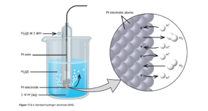
Standard Reduction Potentials (E°) are potentials of the isolated reduction half reactions. Potentials of a half reaction cannot be measured directly. They can only be measured in combination with another half reaction for an overall electrochemical cell. To obtain a value of reduction potential for a half reaction, the standard practice is to measure them in combination with the standard hydrogen electrode (SHE), which is used as a reference and assigned a value of exactly zero volts.
The half reaction for the SHE is :

where the aqueous hydrogen ions have a concentration of 1M, the hydrogen gas has a pressure of 1 atm, and the temperature is 25°C (standard conditions). A picture of the SHE is in OpenStax Figure 17.5:
Other reduction potentials have been measured against the SHE See Figure 17.6 OpenStax) and are tabulated in many locations, including a short list in OpenStax Table 17.1 and more complete listings in OpenStax Appendix L and this periodic table handout (also available in the Unit 4 folder in D2L).
By convention, it is customary to only tabulate reduction potentials. With a table of reduction potentials, a table of oxidation potentials is not needed as the half reaction and sign of the potential are simply reversed to obtain the oxidation potential. For example:


Objective 10:Using tabulated standard reduction potential calculate the standard cell potential (standard EMF) of a galvanic cell and predict whether the reaction is spontaneous.
Objective 11: Given the components of the electrodes and observations on what happens at the electrodes in a voltaic cell, write the balanced oxidation and reduction half reactions, write the balanced overall spontaneous reaction, and calculate the cell voltage.
Let’s consider our earlier example of a galvanic cell: (Figure 17.3 from OpenStax)
Reduction (cathode):
We can look up the reduction potential for the half reaction 
The reduction potential for the half reaction 
Oxidation (anode):
The reduction potential for the reduction
Overall redox reaction
The standard cell potential for the overall reaction (E°cell) is the sum of the oxidation and reduction potential:

An alternative equation to calculate cell potential that you might encounter is: 

You can use either of the above two equations to calculate cell potential. I’d recommend choosing the method you like best and sticking with it.
Objective 10 and 11 Practice
Given the half reactions:
Fe2+ + 2 e– →Fe
MnO4– + 5 e– + 8H+ →Mn2+ + 4 H2O
Answer the following questions:
In a voltaic cell, which one of these reactions would run in reverse (as an oxidation)? Hints:
- Use reduction potential data from this periodic table handout
- Remember for a voltaic cell the overall cell potential must be positive
A voltaic cell is set up with aluminum-aluminum ion as one electrode and nickel-nickel (II) ion as the other. Assuming standard conditions, answer the following questions:
Objective 12: Using standard reduction potentials predict the strength of various oxidizing and reducing agents.
Relative strength of oxidizing and reducing agents
Let’s look at our silver and copper electrochemical cell example again….which was oxidized and which was reduced in the voltaic (spontaneous) cell? Comparing reduction potentials:
The reduction potentials are (from the table):
Ag+ → Ag: Eo = 0.799 V
Cu2+ → Cu: Eo = 0.337 V
In the voltaic cell, Ag+ was reduced and Cu was oxidized.
The silver reduction wants to occur more (has a stronger driving force for reduction) due to its more positive reduction potential. That makes it a stronger oxidizing agent. In a galva2nic (voltaic) cell, the half reaction with the more positive reduction potential will be the reduction (silver in the example), while that with the less positive reduction potential will be the oxidation (copper in this example). This makes the overall cell potential positive, which is indicative of a spontaneous (voltaic) cell.
If you examine a table of reduction potentials (OpenStax Table 17.1 , OpenStax Appendix L , or this periodic table handout ), the species on the left side of the half reactions are being reduced (acting as oxidizing agents). The more positive the reduction potential, the more the driving force for reduction, and the stronger the oxidizing agent. Since the most positive reduction potential on OpenStax Table 17.1 is F2 +2 e– →2 F– at +2.866 V, F2 is the strongest oxidizing agent.
The table can also be used to compare reducing agents. Reducing agents are oxidized, so we must consider the reverse of the reactions on the table. The more positive the oxidation potential, the more the driving force for oxidation , and the stronger the reducing agent. If you use the reductions on the table, the most positive oxidation potential is the most negative reduction potential. And the species being oxidized (reducing agents) are found on the right side of the reductions written on the table. Since the most negative reduction potential on OpenStax Table 17.1 is Li+ + e- →Li at -3.04 V, Li (not Li+) is the strongest reducing agent. Why? Because its reverse (Li→Li+ + e-) would be the most positive oxidation potential.
Objective 12 Practice
Objective 13: Explain the relationship between the maximum cell potential and the free energy difference between cell reactants and products.
The free energy change (ΔG) of a redox reaction and its cell potential E are related by the following equation:

where
- ΔG is free energy change in J
- n is the number of moles of electrons transferred in the balanced redox reaction
- F = 96485 coulombs/mole electrons
- F is called a Faraday
- E is cell potential in volts
If the free energy change is standard, the cell potential is also standard and vice versa:

This equation confirms that a positive cell potential is spontaneous (since it means negative ΔG). Note ΔG and cell potential are always opposite in sign.
This equation also allows ΔG for any redox reaction to be calculated from experimentally determined cell potentials (or the reduction potentials in OpenStax Table 17.1 , OpenStax Appendix L, or this periodic table handout (also available in the Unit 4 folder in D2L).
Objective 13 Example
Calculate ΔGo for the following reaction and indicate whether or not it is spontaneous

We can first break the equation into two half reactions that will add up to give the overall reaction above. That can be done by either identifying the species oxidized and reduced, then adding the electrons in as needed to balance the charge on the half reactions:
- reduction: 4 Ag+ →4 Ag
- balanced reduction: 4 Ag+ + 4 e– →4 Ag
- oxidation: 2 H2O →O2 + 4 H+
- balanced oxidation: 2 H2O →O2 + 4 H+ + 4 e–
Alternatively, you can find two half reactions from a standard reduction potential tablethat add to give the overall redox reaction (remembering that you have to reverse one as an oxidation.
Either method will allow you to break the reaction into half reactions, then using the table (I’m using the one on this periodic table handout ) you can obtain the reduction and oxidation potentials:
reduction: 4 Ag+ + 4 e– →4 Ag E0=+0.799 V
oxidation: 2 H2O →O2 + 4 H+ + 4 e– E0=-1.23 V
overall:
The overall cell potential is:

Note this cell will be an electrolytic (non-spontaneous) cell given the negative voltage. That means we will have a positive ΔG.
Now we can calculate the standard free energy change. Since 4 electrons cancel in the half reactions to give the overall balanced reaction, n=4. For the unit cancellation, remember that 1V = 1 J/C.

The delta G is 
Objective 14: Know and be able to use the equations that relate ΔG°, K and E° for cell reactions.
Objective 16: Qualitatively predict the effect of concentration and gas pressure on cell potential.
Objective 17: Use the Nernst equation to calculate the EMF under nonstandard conditions or to calculate a concentration of reactant or product required to give a certain voltage.
Cell Potential (EMF) under nonstandard conditions
Cell potentials determined using standard reduction potentials are STANDARD cell potentials (Eo). This means all gases are at P= 1 atm and all solutions are 1 M. Consider the redox reaction

with Eo = 0.46 V
What if [Ag+] > 1 M and [Cu 2+ ] = 1 M? We can think of that as adding silver ion to the standard conditions reaction above. LeChatlier’s principle tells us that adding Ag+ would shift the equation right, making it more spontaneous. This will result in a more spontaneous overall redox reaction, with a more negative ΔG than the standard reaction and a more positive cell potential E than 0.46 V. We could get the same result with a Cu2+ concentration of <1M, which would be like removing Cu2+
Conversely, if [Cu 2+] > 1 M and [Ag+] = 1 M, we would expect a cell potential of <40.6 V.
Calculating nonstandard cell potential using the Nernst Equation
In your previous study of thermodynamics, you learned to calculate nonstandard ΔG from standard ΔG° using this equation:

Substitituting -nFE for ΔG and -nFE° for ΔG° and rearranging algebraically gives the same equation in terms of cell potential:

- E = cell potential (nonstandard conditions)
- E° = call potential (standard conditions)
- R = 8.3145 J/ mol·K
- T = Kelvin temperature
- Q = reaction quotient
This equation is known as the Nernst Equation.
A simplified form of the Nernst Equation (only valid at 298 K) often encountered is:

This equation is a remnant of the time when calculators were not readily available and simplifies the calculation. The 0.0592 comes from the numerical values for F and R, 298 for T, and a conversion from natural log ln to a base 10 log. If you use the simplified equation, be sure to use log Q, not ln Q.
Calculations using the Nernst equation will be similar to those of nonstandard ΔG in thermodynamics. You will have a chance to try one in the practice problems later
Concentration, Ecell, ΔG, and relative spontaneity
As a voltaic cell is discharged, the reactants are consumed and products are generated, and the concentration of the reactants and products change. This changes the value of Q and gradually decreases the nonstandard cell potential. The cell will continue to run spontaneously until E decreases to zero. At which point, equilibrium has been reached and the reaction and cell will no longer run spontaneously. The cell is then “dead.” This is what happens when batteries (which are electrochemical cells) die.
The point at which E = 0 is determined by the concentrations of the species involved in the redox reaction.
Objective 17 Practice
Using standard reduction potential values from this periodic table handout , calculate the cell potential for the following reaction at 25°C :
2 Al(s) + 3 Mn2+ (aq) → 2 Al3+ (aq) + 3 Mn(s)
when [Mn2+] = 0.50 M and [Al3+] = 1.50 M
E°cell & the Equilibrium Constant K
In your previous study of thermodynamics, you also learned learned the relationship between the equilibrium constant K and standard free energy ΔG°:
ΔG° = -RT ln K
The cell potential or Nernst Equation versions of this equation are:


Objective 14,16,17 practice
Using standard cell potentials, calculate the equilibrium constant for the reaction below at 25°C.

Calculate Ksp for Ag2CrO4 given the following:


Objective 15: Explain the basis for concentration cells.
A concentration cell is one whose emf is generated solely because of a concentration difference. Both the cathode and anode contain the same electrode and the same solution, so the half reactions are the same (but opposite direction) and the standard cell potential is zero. However, with different molarities if the ion solutions, a nonstandard cell potential that is nonzero exists and current is generated. See Example 17.8 in OpenStax Section 17.4 for an example.
Objective 18: Explain with the aid of the balanced equation the operation of fuel cells and of the lead-acid, alkaline, the nickel-cadmium, nickel-metal hydride, and lithium-ion batteries.
Objective 19: Distinguish between batteries and fuel cells.
Objective 20: Explain the electrochemical nature of corrosion and describe some methods of preventing it.
These objectives cover applications of electrochemistry. Quiz 6 gives you an opportunity to address these applications and objectives
Objective 21: Explain the difference in product at each electrode for molten salts compared to aqueous solutions of the salt.
Objective 22: Using standard reduction potentials predict the most likely product at each electrode in the electrolysis of aqueous solutions and write the equation for the reaction.
Electrolysis
Forcing a current through an electrochemical cell to force a reaction for which the cell potential is negative (electrolytic cell)
- In an electrolytic cell, reduction occurs at the cathode and oxidation occurs at the anode (same as in a galvanic or voltaic cell)
This table summarizes facts you have learned about voltaic and electrolytic cells:
| Voltaic Cell | Electrolytic Cell | |
| Ecell | positive | negative |
| ΔG | negative | positive |
| Spontaneous? | yes | no (is forced) |
| Cathode | positive | negative |
| Anode | negative | positive |
Electrolysis of compounds
An example of electrolysis is the Downs cell, which is used to produce metallic sodium and chlorine gas. Figure 17.18 in OpenStax shows a schematic of the downs cell with the oxidation and reduction half reactions:
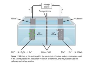
Sodium is produced at the cathode (reduction) and chlorine gas is produced at the cathode (oxidation). Adding the two half reactions together yields the overall reaction of:
2 Na+ + 2Cl– →2Na + Cl2
This is sometimes written as 2NaCl→2Na + Cl2
As an electrolytic cell, the overall cell potential will be negative (you should be able to figure it out using half reactions).
The compound NaCl was split into its neutral elements during electrolysis. This is often the case. The electrolysis of water is a good example. In the electrolysis of water, O2 is produced at the anode and H2 is produced at the cathode.
| Oxidation: | 2H2O → O2 + 4H+ + 4e– | E0 = -1.23 V |
| Reduction: | 4H2O + 4e– → 2H2 + 4OH– | E0 = – 0.83 V |
| Overall or net: | 2H2O → 2H2 + O2 | E0 = -2.06 V |
Electrolysis of molten salts
The Downs cell is an example of the electrolysis of a molten salt (the salt is in a liquid phase at a high temperature – it is not dissolved in water or another solvent). As another example, the reactions for the electrolysis of CaBr2 (l) is shown below:
In this cell, Br2 is produced at the anode and Ca is produced at the cathode
| Oxidation: | 2Br– → Br2 + 2e– | E0 = -1.06 V |
| Reduction: | Ca2+ + 2e– → Ca | E0 = -2.76 V |
| Overall or net: | CaBr2 → Ca + Br2 | E0 = -3.82 V |
Electrolysis of Aqueous Salt Solutions: CaBr2 (aq)
What happens if an aqueous solution of a salt, as opposed to the pure molten salt, undergoes electrolysis? Now there are two possible reactions at each electrode. At the cathode, either the hydrogen from water or the metal from the salt can be reduced. At the anode, either the oxygen from the water or the anion from the salt can be oxidized. Overall, sometimes both of the salt reactions occur, other times, both of the water reactions occur, and sometimes the salt half reaction can occur at one electrode while the water one occurs at the other. How do we know what will occur? Let’s look at an example for CaBr2(aq):
The half reactions of the salt and water compete at both the cathode and anode. Which half reaction occurs at each anode will usually be decided by E0 (more positive will occur). The most positive (least negative) reduction potential occurs at the cathode. The most positive (least negative) oxidation potential occurs at the anode.
In this cell, we would predict that Br2 is produced at the anode and H2 is produced at the cathode
| Oxidation: | 2H2O → O2 + 4H+ + 4e– or
2Br– → Br2 + 2e– |
E0 = -1.23 V or
E0 = -1.06 V |
| Reduction: | 4H2O + 4e– → 2H2 + 4OH– or
Ca2+ + 2e– → Ca |
E0 = – 0.83 or
E0 = – 2.76 |
Objective 21 and 22 Practice
Objective 23: Given two of the three following variables: time, current or amount of substances reacting in an electrolytic cell, calculate the third variable. Amount can be indicated by grams, volume, moles, concentration, pH, pOH, molar mass, or oxidation state
Objective 24: Explain how electrolysis can be used in the application of metal plating.
In electroplating, a metal ion in solution is reduced to its solid, elemental form and “plated” or deposited onto a cathode surface. This is common for jewelry, silverware, and other applications. This is done by supplying the electrons needed for a reduction using an electrical current.
Current is defined as the amount of charge passing a point in a circuit in one second. The unit of current is an ampere (A). An ampere is often called “amp”.

Quantitative Aspects of Electrolysis
We can calculate how much chemical change occurs with the flow of a given electrical current for a specific time (in other words, we can calculate how much metal can be plated from a metal ion solution. This is most easily done via dimensional analysis. When using dimensional analysis, recall that
and 1 mol e– = 96485 C.
Example: Quantitative Aspects of Electrolysis
How much solid copper will be deposited (“plated out” ) when a current of 10.0 A is passed through a Cu2+ solution for 30.0 minutes?
Cu2+ + 2e– → Cu
This reduction equation gives a stoichiometric ratio of 1 mol Cu plated to 2 moles of electrons.
We can start with our time of 30.0 minutes, and use the given information and conversion factors to convert to the desired mass in grams:

You should be able to work these problems in other combinations — for example, if asked how long would it take in minutes to plated out 5.93 g Cu when a current of 10.0 A is passed through a Cu2+ solution you should be able to work through the problem backwards and calculate 30.0 minutes.
For these problems, some students prefer to use an equation : this works as well

where
- m is mass plated in grams
- t is time in seconds
- I is current in amps
- μ is molar mass in g/mol
- n is moles of electrons in the reduction half reaction
- F=96485 C/mol electrons
Objective 23 Practice
For the anode reaction Cd + 2OH– → Cd(OH)2 + 2e– , how much cadmium would be used up at the anode in the delivery of 0.100 amperes of electrical current for 30 hours?
An aqueous solution of an unknown salt of ruthenium is electrolyzed by a current of 2.50 A passing for 50.0 min. If 2.618 g of Ru is produced at the cathode, what is the charge on the ruthenium ion in solution?
What’s next?
This concludes our look at electrochemistry. Next up is our final topic of the semester – molecular orbitals.